
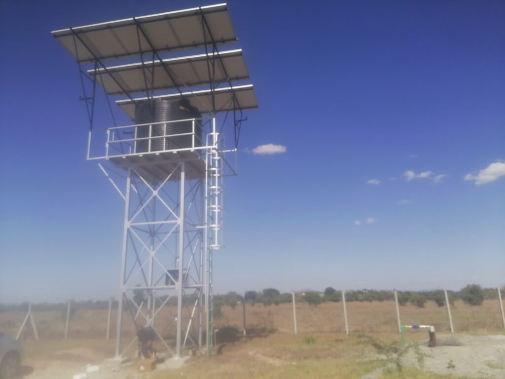
Wind is usually the controlling lateral load on an elevated water tower. The tank is a large, bluff body perched high above the ground, and the pressure there is far greater than at ground level. Add a solar panel array and the wind area grows again. Getting the wind calculation right protects the tower from overturning and the foundation from uplift, while avoiding unnecessary steel. This article explains how wind loads are calculated using the Eurocode and the ASCE 7 approach, and how the TIA-222 method relates to water towers.
Which Standard Applies?
- Eurocode EN 1991-1-4 gives wind actions and is used with EN 1993-4-2 (tanks) and EN 1993-3-1 (towers).
- ASCE 7 is the US loading standard and is referenced by AWWA D100 for tanks and elevated water storage.
- ANSI/TIA-222 is written for antenna-supporting structures. It is not the governing standard for water towers, but its procedure for lattice frames is similar to ASCE 7, and it is sometimes used for the supporting frame when the tower also carries antennas. For water towers, use ASCE 7 or the Eurocode, or the local building code and the tank standard.
Always confirm which code the project, the client and the local authority require, and apply one consistently.
How Wind Acts on a Water Tower
Wind pushes on:
- The tank, a large cylinder or box with a roof.
- The tower frame, legs and bracing, with lower area but extra exposure to solid-looking panels in monopoles.
- Solar panels, with pressure and suction depending on tilt and position.
- Ladders, platforms and pipes.
Wind speed increases with height, so the tank near the top receives the highest pressure, and the lever arm to the base is large.
The general formula is:
Force = Pressure × Area × Force coefficient × Gust factor
Eurocode Method (EN 1991-1-4)
- Basic wind velocity: vb = cdir × cseason × vb,0, where vb,0 is the fundamental value from the National Annex or a local map.
- Mean wind velocity at height z: vm(z) = cr(z) × co(z) × vb, with cr(z) = kr ln(z/z0).
- Turbulence intensity: Iv(z) = kI / [co(z) ln(z/z0)].
- Peak velocity pressure: qp(z) = [1 + 7 Iv(z)] × ½ ρ vm²(z), with ρ = 1.25 kg/m³.
- Wind force: Fw = cs cd × cf × qp(ze) × Aref.
Terrain categories range from 0 (sea) to IV (urban), each with its own roughness length.
Worked example (simplified). A tank centre at 15 m, terrain category II (z0 = 0.05 m), vb = 28 m/s:
- kr = 0.19, cr(15) = 0.19 × ln(15/0.05) ≈ 1.08
- vm ≈ 1.08 × 28 ≈ 30.3 m/s
- Iv ≈ 1/ln(300) ≈ 0.175
- qp ≈ (1 + 7 × 0.175) × 0.5 × 1.25 × 30.3² ≈ 1,280 N/m²
For a cylindrical tank of diameter 3 m and height 3 m, the projected area is about 9 m², so with cf of roughly 0.7 to 1.0 depending on the aspect ratio and roughness, the wind force is about 8 to 11 kN, acting at about 16.5 m above ground. Add the tower frame and solar panels.
ASCE 7 Method (Used with AWWA D100)
- Basic wind speed (V): three-second gust at 10 m from the map for the risk category.
- Exposure category: B (urban and suburban), C (open terrain), D (flat open coastal areas).
- Velocity pressure exposure coefficient Kz: Kz = 2.01 (z/zg)^(2/α), with α = 9.5 and zg = 274.32 m for Exposure C.
- Topographic factor Kzt, ground elevation factor Ke and directionality factor Kd (about 0.95 for round tanks).
- Velocity pressure: qz = 0.613 × Kz × Kzt × Ke × Kd × V² (N/m², V in m/s).
- Design force: F = qz × G × Cf × A.
Worked example (simplified). Exposure C, V = 40 m/s, z = 15 m, Kzt = Ke = 1.0:
- Kz ≈ 2.01 × (15/274.32)^0.2105 ≈ 1.09
- qz ≈ 0.613 × 1.09 × 0.95 × 1,600 ≈ 1,016 N/m²
Then apply the gust factor and force coefficient for the tank shape, and add the frame.
These examples are illustrative. The Eurocode and ASCE 7 define wind speed differently (10-minute mean versus 3-second gust) and use different return periods and partial factors, so their pressures are not directly comparable.
Force Coefficients
- Cylindrical tanks: the coefficient depends on the height-to-diameter ratio and surface roughness. Typical values range from about 0.5 to 1.2.
- Rectangular tanks: coefficients are higher, commonly 1.2 to 2.0 for a flat face.
- Roofs: domed and conical roofs experience suction, so check connections to the walls.
- Lattice frames: depend on solidity ratio, shape and wind direction.
- Open frames below a tank may be partly shielded, but this should only be assumed where the code allows.
Solar Panels on or Near the Tower
Panels experience both pressure and suction. Tilted panels in open positions can face net uplift larger than the panel weight. ASCE 7-16 includes provisions for ground-mounted and roof-mounted solar arrays, and the Eurocode gives pressure coefficients for free-standing monopitch canopies that are often used as a basis. Panel edges and corners see higher loads. Frames and connections must resist uplift, and the whole array load must be added to the tower overturning moment if mounted on it. Manufacturer data sheets state the maximum test load, typically 2,400 Pa to 5,400 Pa, which must exceed the design wind pressure.
Full Tank and Empty Tank Cases
- Full tank: the maximum vertical load and settlement check.
- Empty tank: the minimum stabilising weight, the governing case for overturning, anchor bolts and uplift.
- Check combinations such as 0.9 × dead load + 1.0 × wind (uplift) and 1.2 × dead load + 1.6 × wind + liquid load, subject to the factors in the code used.
Seismic Loads and Sloshing
In regions such as parts of the Rift Valley, seismic loading may govern some members. Water movement during an earthquake has two parts: an impulsive mass that moves with the tank, and a convective mass that sloshes. Codes such as EN 1998-4 and AWWA D100 provide procedures. Sloshing needs adequate freeboard so water does not hit the roof.
Local Wind Data in Kenya
Design wind speed should come from a recognised source or project specification. Kenya Meteorological Department records, international maps and regional guidance may be used. Exposed escarpments, hilltops, lake shores and coastal sites have higher wind. Topographic effects should be included, and the chosen basis clearly documented.
Common Mistakes
- Using the telecom code without justification.
- Forgetting wind on the tank because the tower is the focus.
- Ignoring the empty-tank case.
- Underestimating solar panel uplift.
- Mixing wind speeds from different codes.
- Not checking the roof and its connection to the shell.
Conclusion
Wind load calculation for a water tower is a clear chain: choose the wind speed and terrain, convert to pressure at the height of the tank and frame, then apply shape and gust factors to the exposed area. Include solar panels, check the empty-tank case and design the foundation for uplift. Document every assumption and have a qualified structural engineer review the results.
Key references: EN 1991-1-4; EN 1993-4-2; EN 1993-3-1; EN 1998-4; ASCE 7-16; AWWA D100; ANSI/TIA-222-H (for comparison of method).
