
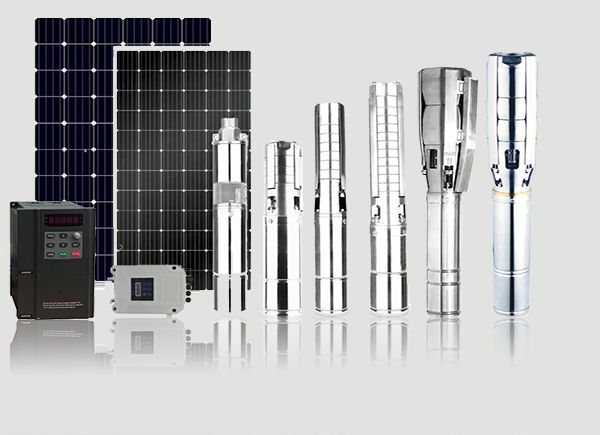
Pumps are among the biggest electricity users in water supply, buildings, farms and industry. A variable frequency drive (VFD) lets a pump motor run at the speed the system actually needs, instead of at full speed with a throttled valve. Used well, a variable frequency drive for pumps can cut energy use sharply, reduce wear and make pressure control smoother. This guide explains how the savings work, where they do not, and how to set a drive up.
What Is a VFD and How Does It Work?
An AC induction motor turns at a speed set by the supply frequency and the number of motor poles. A VFD converts incoming AC to DC and then synthesises a new AC output with adjustable frequency and voltage. Lower frequency means lower motor speed, and the drive reduces voltage in proportion so the motor does not overheat. Kenya’s supply is 50 Hz, so a standard 4-pole motor runs at about 1,450 rpm at full frequency, and the drive can run it slower, or slightly faster within the motor’s limits.
Why Slowing a Pump Saves So Much Energy: The Affinity Laws
For centrifugal pumps, three relationships link speed to performance:
- Flow changes in direct proportion to speed.
- Head (pressure) changes with the square of speed.
- Power changes with the cube of speed.
The cube law is the source of the savings. Reducing speed to 80% of full speed gives about 80% of the flow but only about 51% of the power (0.8³ = 0.512). At 50% speed, flow is half but power falls to about one eighth.
Compare this with the traditional alternative, throttling a valve. A throttled pump still runs at full speed and burns the excess energy as friction in the valve. Energy-efficiency programmes report that motor-driven systems such as pumps, fans and compressors account for a large share of industrial electricity use, which is why variable speed control is one of the most common efficiency upgrades.
When Does a VFD Make Sense?
A VFD saves the most when:
- Demand varies through the day or season, for example building water boosting, irrigation zones, process cooling and municipal supply.
- The pump is oversized and is being throttled or run through a bypass.
- System friction dominates rather than static lift.
- Pressure must be held constant as demand changes.
- Soft starting is valuable to reduce water hammer and electrical stress.
A VFD saves little when:
- The pump runs at full flow nearly all the time.
- The system is almost entirely static head, such as pumping up a tall hill into a tank, because the pump cannot slow down much before it stops delivering water. Below a certain speed the pump head falls below the static lift and flow drops to zero.
Plan the speed range from the system curve, not just the pump curve.
Estimating the Savings
A simple example shows the idea. Suppose a 15 kW booster set runs ten hours a day with demand that averages 70% of full flow. At 70% speed, the power is about 0.7³ ≈ 34% of full power, so roughly 5 kW instead of 15 kW. In practice, motor, pump and drive efficiencies fall at low speed, and a system with static head will save less, so a realistic saving might be 20 to 50% of the pump’s energy depending on the load profile. If the energy price is KES 20 per kWh, a 5 to 8 kW saving over 3,000 operating hours a year is worth roughly KES 300,000 to 480,000 a year. These are illustrative numbers. Use a load profile for your own site, and obtain quotes for the drive, panel and installation, to calculate payback.
Other Benefits Beyond Energy
- Soft start and stop: the drive ramps the motor up and down, reducing inrush current (a direct-on-line start can draw six to eight times full-load current) and cutting water hammer.
- Constant pressure control: the drive adjusts speed to hold set pressure, improving service and reducing leaks caused by pressure spikes.
- Reduced mechanical wear: lower speeds reduce bearing and seal loads and noise.
- Built-in protection and monitoring: modern drives monitor current, voltage, temperature and often flag dry running or blocked pumps.
- Duty-standby and multi-pump control: many drives can stage and alternate pumps.
Limitations and Cautions
- Minimum speed: most pumps need to stay above about 30 to 40% speed to maintain flow for motor cooling, bearing lubrication, and to avoid operating far from their best efficiency point. Submersible motors depend on water flow past the motor for cooling, so follow the manufacturer’s minimum frequency.
- Harmonics: drives inject harmonic currents into the supply. Large installations may need line reactors or filters.
- Motor insulation stress: fast voltage switching can stress motor windings, especially with long cables. Use inverter-duty motors or output filters (dv/dt or sine filters) for long cable runs, particularly with submersible motors.
- Resonance: the variable speed range may pass through critical speeds of the pump, piping or structure. Use the drive’s skip-frequency feature to avoid them.
- Cost and heat: drives are electronic, need clean ventilated enclosures and dissipate heat. High ambient temperatures and dust shorten life.
- Static head systems: as noted above, savings are limited.
Step-by-Step VFD Setup for a Pump
- Check the match. The drive’s output current rating must exceed the motor’s full-load current, and the motor insulation should suit drive operation. For submersibles, confirm the drive and cable length are approved by the motor maker.
- Install correctly. Mount the drive in a clean, ventilated, cool location with the clearances in the manual. Use the recommended input protection and screened motor cable, and ground the screen at both ends as instructed. Keep control cables away from power cables.
- Enter motor nameplate data: rated voltage, current, frequency, speed (rpm) and power. Run the motor identification or auto-tune routine if available.
- Set speed limits: minimum frequency (often 30 to 35 Hz for submersibles, or as advised by the manufacturer) and maximum frequency (normally 50 Hz).
- Set ramp times: use longer acceleration and deceleration times, often 10 to 30 seconds or more, to limit water hammer. On long pipelines, a slow stop is critical.
- Select the control mode: use the pump-specific or quadratic V/f curve if the drive offers one, which gives energy savings at part load.
- Configure PID control: connect a pressure or flow transmitter, set the setpoint, and tune gains. Start with low proportional gain and add integral action slowly to avoid hunting.
- Enable protections: overload, dry-run (low-current) detection, under- and over-voltage, phase loss, over-temperature and, where applicable, sleep or boost functions to stop the pump at no demand.
- Set skip frequencies if vibration testing finds resonance bands.
- Test and commission: run the pump through its speed range, record current, pressure and vibration, check for noise or instability, and save the parameter backup.
Maintenance and Good Practice
- Keep drive cooling air paths and filters clean.
- Check connections and fans at least annually.
- Back up parameters and label the drive with its settings.
- Review trends: rising current or temperature at the same speed signals pump wear or blockage.
- Follow the manufacturer’s guidance on capacitor life and replacement intervals.
Conclusion
A variable frequency drive for pumps can cut energy use, protect equipment and give steady pressure, especially where demand varies and friction head dominates. The savings come from the cube law, but they depend on the system curve, the minimum safe speed and a careful setup. Size the drive properly, protect the motor, tune the control loop and confirm the payback with your own load data.
Sources and Further Reading
- Pumps & Systems, “VFDs Save Energy in Pump Applications”: pumpsandsystems.com
- U.S. Department of Energy, Advanced Manufacturing Office, pumping system resources: energy.gov
- Hydraulic Institute and Europump, “Variable Speed Pumping: A Guide to Successful Applications”: pumps.org
- IEC 61800-9, adjustable speed electrical power drive systems, energy efficiency: iec.ch
