
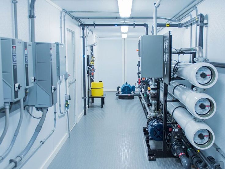
A well-designed pump room makes pumps easier to run, cheaper to maintain and far less likely to fail. A poorly laid-out one causes cavitation, noise, flooding, overheating and awkward repairs that cost more than the equipment saved. This guide sets out practical pump room design and layout guidelines that apply to water supply, building services, industrial and irrigation pump houses, drawing on common hydraulic and mechanical engineering practice.
Start With the Duty and the Standards
Before drawing the room, define:
- Duty points: flow and head for each operating condition, including future expansion.
- Redundancy: a duty/standby arrangement (N+1) is common for critical supplies, where one pump can fail without losing service.
- Pump type: horizontal end-suction, split-case, vertical multistage, inline or submersible, since each has different space and piping needs.
- Applicable standards: the Hydraulic Institute standards (for example ANSI/HI 9.8 for intake and sump design) and local building, fire and electrical codes. For fire pumps, NFPA 20 has its own detailed requirements (see our separate guide).
Plan the Space: Clearances and Access
Leave enough room to operate and, importantly, to remove equipment:
- Keep at least about 1 metre of clear working space around each pump and motor, more for large units.
- Allow space to withdraw the motor, coupling guard and impeller, and for a bearing or seal change, along the axis of the shaft for split-case pumps.
- Provide a lifting arrangement such as a monorail, gantry or hoist beam, rated for the heaviest component, and a clear route from the door to every pump.
- Make doors wide enough for the largest component, or provide a removable roof or hatch.
- Leave room in front of electrical panels, typically at least 1 metre, to meet electrical safety rules.
Plan the layout so that pumps are in a line with consistent spacing, with the suction manifold on one side and the discharge manifold on the other. It keeps pipework simple and makes future pumps easy to add.
Foundations and Mounting
Vibration starts at the base. Good practice includes:
- A concrete foundation block heavier than the pump and motor, often designed at roughly two to three times their combined weight, and extending beyond the baseplate.
- Grouted baseplates, levelled and leaving no voids.
- Anti-vibration mounts or flexible connections where noise or vibration transfer to the building is a concern.
- Separate pipe supports so that pipe weight does not rest on the pump flanges. Pipe strain is a leading cause of misalignment and seal failure.
- A foundation that is isolated from the building structure for large machines or sensitive buildings.
Suction Piping: The Most Important Design Detail
Poor suction conditions are behind many cavitation and vibration problems.
- Keep suction pipes short, straight and one size larger than the pump inlet where possible.
- Provide a straight run of pipe before the suction flange, commonly around five to ten pipe diameters, so flow enters the impeller evenly.
- Use eccentric reducers with the flat side up on horizontal suction lines to avoid air pockets.
- Slope suction lines to avoid trapping air, and avoid elbows directly at the pump inlet.
- Keep suction velocities low, as a rule of thumb about 1 to 2 metres per second.
- Check that the available net positive suction head (NPSH) exceeds the pump’s requirement with a margin. Altitude and water temperature reduce it, which matters for Kenyan highland sites.
- Where pumps draw from a sump or tank, follow the minimum submergence, spacing and wall clearances in the Hydraulic Institute intake guidance to avoid vortices and air entrainment.
Discharge Piping and Valves
- Install, in order from the pump outwards: a reducer or increaser as needed, a non-return (check) valve, and an isolation valve.
- Use isolation valves on both suction and discharge so each pump can be taken out of service.
- Keep discharge velocities moderate, as a rule of thumb about 2 to 3 metres per second.
- Fit pressure gauges on suction and discharge, and consider flow metering for performance monitoring.
- Add surge protection (air vessels, surge relief or slow-closing valves) where water hammer is a risk, particularly on long pipelines and with fast-closing check valves.
- Include a bypass or test connection if you need to check pump performance without disrupting the system.
- Design flexible couplings or expansion joints where thermal movement or vibration is expected, with proper restraint.
Drainage and Flood Protection
Pump rooms often sit below ground and handle water, so assume leaks will happen.
- Provide a floor with slope to a drain or sump, and a sump pump with a high-level alarm for below-ground rooms.
- Raise motors and panels on plinths above the floor.
- Keep floor drains clear and provide a way to drain the pumps for maintenance.
- Consider flood levels, rainwater entry through doors and stairwells, and a backflow preventer if the drain connects to the sewer.
Ventilation and Temperature Control
Motors turn a share of the electrical energy into heat, and a hot room reduces motor life and drive reliability.
- Estimate the heat load from motor and drive losses and size ventilation to keep the room within the temperature limits of the equipment, typically below about 40°C ambient for standard motors and drives.
- Use natural ventilation with louvres where possible, or mechanical extract fans.
- Keep ventilation openings away from rain entry and protect them with insect screens.
- For rooms with diesel engines or sewage equipment, add specific ventilation for exhaust, combustion air and gas hazards.
Electrical Layout
- Locate control panels and VFDs where they are easy to reach but protected from water and heat. Many designers put them in a separate, ventilated electrical room or on a raised, enclosed panel with a suitable ingress protection (IP) rating.
- Separate power and instrumentation cables to avoid noise, and use screened cable for drive output where required.
- Provide lighting that is bright enough for inspection, with emergency lighting for safe exit.
- Include earthing and bonding for all metal parts, with lightning and surge protection where the site is exposed.
- Add a local isolator near each motor so it can be locked off for maintenance.
Noise Control
Pump rooms close to occupied spaces need attention to noise:
- Use properly selected, balanced pumps running near their best efficiency point.
- Use flexible connectors and vibration isolators.
- Locate the room away from bedrooms and quiet areas where possible, or add acoustic insulation to walls and doors.
- Consider variable speed operation, which often reduces noise at partial flow.
Safety and Compliance Features
- Guards on all rotating parts, including couplings.
- Clear signage for valves, electrical isolation and emergency procedures.
- Fire protection appropriate to the building, including extinguishers and, where required, detection.
- Safe access with non-slip floors and handrails for stairs and pits.
- Confined space controls for deep pits and sumps, especially for wastewater.
- Drawings, valve schedules and operating instructions kept in the room.
A Simple Layout Template
        [Door / lifting route]
 -----------------------------------------
 | Suction manifold  ====================== |
 |      |         |          |             |
 |   [Pump 1]  [Pump 2]  [Standby pump]    |
 |      |         |          |             |
 | Discharge manifold ==================== |
 |                                         |
 | [Control panel / VFDs]   [Sump + drain] |
 -----------------------------------------
Common Design Mistakes
- Squeezing pumps so tightly that motors cannot be removed.
- Using suction pipes smaller than the pump inlet, or fitting an elbow directly at the inlet.
- Letting pipe weight hang on pump flanges.
- Forgetting drainage and ventilation.
- Placing panels where leaks or condensation can reach them.
- No provision for a standby pump or future expansion.
Conclusion
Good pump room design and layout comes down to generous access, a solid foundation, clean suction piping, supported pipework, drainage, ventilation and safe electrics. Spend time on these details at the design stage and the pumps will run closer to their best efficiency, last longer and be much easier to maintain. Always check the final design against the pump manufacturer’s instructions and local codes.
Sources and Further Reading
- Hydraulic Institute, ANSI/HI standards including HI 9.8 (pump intake design): pumps.org
- Water Technology, “Understanding Vibration Can Help Prevent Pump Failures”: watertechonline.com
- National Fire Protection Association, NFPA 20 (fire pump rooms): nfpa.org
- Kenya Bureau of Standards (KEBS): kebs.org
