
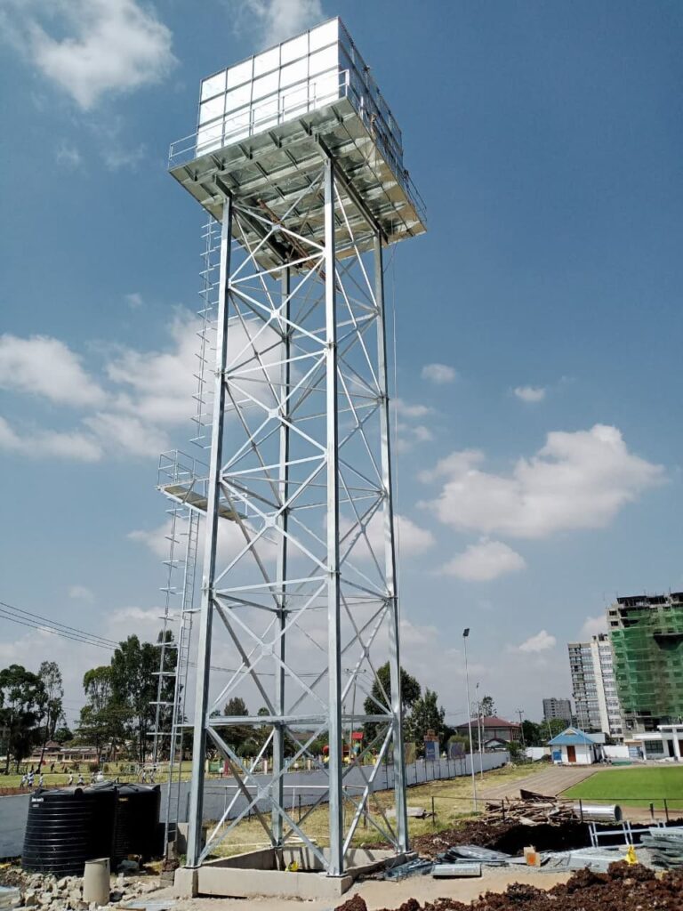
Wind is the dominant load on almost every telecom or broadcast tower. A small error in wind calculation can mean an unsafe structure or an unnecessarily expensive one. Two design frameworks are widely used around the world: ANSI/TIA-222 in North America and many telecom projects globally, and the Eurocode system (EN 1991-1-4 for wind actions with EN 1993-3-1 for tower design) in Europe and many other countries. This article explains how each works, with simplified worked examples.
How Wind Acts on a Tower
Wind pushes on every exposed surface: structural members, antennas, dishes, ladders, cables and platforms. The force depends on air density, wind speed squared, the area exposed and a shape factor known as the force or drag coefficient. Wind speed itself increases with height and varies with terrain roughness, so the top of the tower sees the highest pressure. Gusts and the dynamic response of the tower add further amplification.
The general form of all wind calculations is:
Force = Pressure × Area × Shape factor × Gust factor
The TIA-222-H Approach
ANSI/TIA-222-H is the current revision of the Structural Standard for Antenna Supporting Structures, Antennas and Small Wind Turbine Support Structures. Its main steps are:
1. Choose the structure class. Class I covers structures where failure poses low risk, Class II covers those with substantial economic impact or service importance, and Class III covers critical services or structures where failure threatens life. Higher classes use higher design wind speeds.
2. Obtain the basic wind speed (V). This is a three-second gust at 10 m above ground, taken from the standard’s wind maps or the relevant local reference.
3. Select the exposure category. Exposure B is urban or wooded terrain, C is open terrain with scattered obstructions, and D is flat unobstructed coastal or water areas.
4. Calculate the velocity pressure coefficient (Kz). It increases with height: Kz = 2.01 (z/zg)^(2/α), where z is height above ground, and α and zg depend on exposure (for Exposure C, α = 9.5 and zg = 274.32 m).
5. Apply topographic factor (Kzt). This increases pressure on hills, ridges and escarpments.
6. Apply other factors. These include the ground elevation factor (Ke), wind directionality (Kd, about 0.95 for many tower types) and the gust response factor (Gh).
7. Compute velocity pressure: qz = 0.613 × Kz × Kzt × Ke × V² (in N/m², V in m/s) and multiply by Kd where applicable.
8. Compute force on each element: F = qz × Gh × (CF × AE), where CF is the force coefficient for the shape and AE the effective projected area.
9. Include ice and combination cases if relevant, and check serviceability wind.
TIA-222-H also integrates structural condition assessment, inspection rules and requirements for the design of foundations, which makes it a complete system for communication structures.
The Eurocode Approach
In the Eurocode system, wind actions come from EN 1991-1-4, and the tower structure is checked using EN 1993-3-1.
1. Basic wind velocity: vb = cdir × cseason × vb,0, where vb,0 is the fundamental value from the National Annex or local map (10-minute mean at 10 m in terrain category II).
2. Mean wind velocity at height z: vm(z) = cr(z) × co(z) × vb, where cr(z) = kr ln(z/z0) is the roughness factor and co is the orography factor.
3. Turbulence intensity: Iv(z) = kI / [co(z) ln(z/z0)].
4. Peak velocity pressure: qp(z) = [1 + 7 Iv(z)] × ½ ρ vm²(z), with air density ρ = 1.25 kg/m³.
5. Wind force: Fw = cs cd × cf × qp(ze) × Aref, where cs cd is the structural factor, cf is the force coefficient and Aref is the reference area.
Terrain categories run from 0 (sea) to IV (urban areas with tall buildings), each with its own roughness length z0.
Worked Example 1: TIA-222 (Simplified)
Assume a 40 m lattice tower in open terrain (Exposure C) with a basic wind speed of 40 m/s, Kzt = 1.0, Ke = 1.0.
- Kz at 40 m = 2.01 × (40/274.32)^(2/9.5) ≈ 2.01 × 0.667 ≈ 1.34
- qz = 0.613 × 1.34 × 1.0 × 1.0 × 40² ≈ 1,314 N/m²
- With Kd = 0.95, design pressure ≈ 1,248 N/m²
The final force then depends on the area and gust factor.
Worked Example 2: Eurocode (Simplified)
Assume the same 40 m height in terrain category II (z0 = 0.05 m), vb = 28 m/s, cdir = cseason = co = 1.0.
- kr = 0.19, so cr(40) = 0.19 × ln(40/0.05) ≈ 1.27
- vm = 1.27 × 28 ≈ 35.6 m/s
- Iv = 1/ln(40/0.05) ≈ 0.15
- qp = (1 + 7 × 0.15) × 0.5 × 1.25 × 35.6² ≈ 1,621 N/m²
These are illustrative only. The two codes use different wind speed definitions (3-second gust versus 10-minute mean), different return periods and different partial factors, so pressures cannot be compared directly without converting.
Force Coefficients for Lattice Towers
For lattice towers, the force coefficient depends on solidity ratio, the proportion of the projected face that is filled by steel, and on member shape. Round members have lower drag than flat-sided angles. Towers with low solidity (open frames) have higher coefficients per unit area but smaller total area. Both standards provide equations or tables for square and triangular towers and wind direction effects, with the worst direction often being along the diagonal for square towers.
For monopoles, the coefficient depends on the cross-section shape, surface roughness and Reynolds number. Multi-sided sections have different coefficients than round ones.
Antennas, Cables and Appurtenances
Appurtenances often contribute 30 to 60 percent of the total wind force on a loaded tower. Each antenna has manufacturer-supplied wind data, and dishes have forces that vary with angle. Cables should be included as bundles with their own coefficients. Under TIA-222-H, shielding effects between closely spaced items are permitted only under defined rules.
Dynamic Effects
Very tall or slender towers can respond dynamically, especially to vortex shedding in tubular shafts. Both codes include gust or structural factors to account for amplification, and Eurocode provides procedures to check for vortex-induced vibration.
Local Conditions in Kenya
Design wind speed in Kenya is usually specified by the project or derived from meteorological records and regional design guides, since the Eurocode National Annex and TIA maps do not directly cover the country. Escarpments in the Rift Valley, the Kenyan coast, and the high ground around Mount Kenya and the Aberdares may experience stronger or more turbulent winds. Topographic and exposure effects should be considered carefully, and the chosen wind basis should be clearly documented.
Common Mistakes
- Mixing wind speeds from different codes.
- Ignoring future antenna loading.
- Omitting topographic effects for hilltop sites.
- Using the wrong exposure category.
- Failing to include ice or cable loading where relevant.
Conclusion
Wind load calculation follows a logical chain: select a wind speed, adjust for height and terrain, convert to pressure, then apply shape and gust factors to the exposed area. TIA-222 and Eurocode use different details but the same principle. Always document assumptions, use verified equipment data, and have the calculation checked by a qualified structural engineer.
Key references: ANSI/TIA-222-H; EN 1991-1-4; EN 1993-3-1.
