
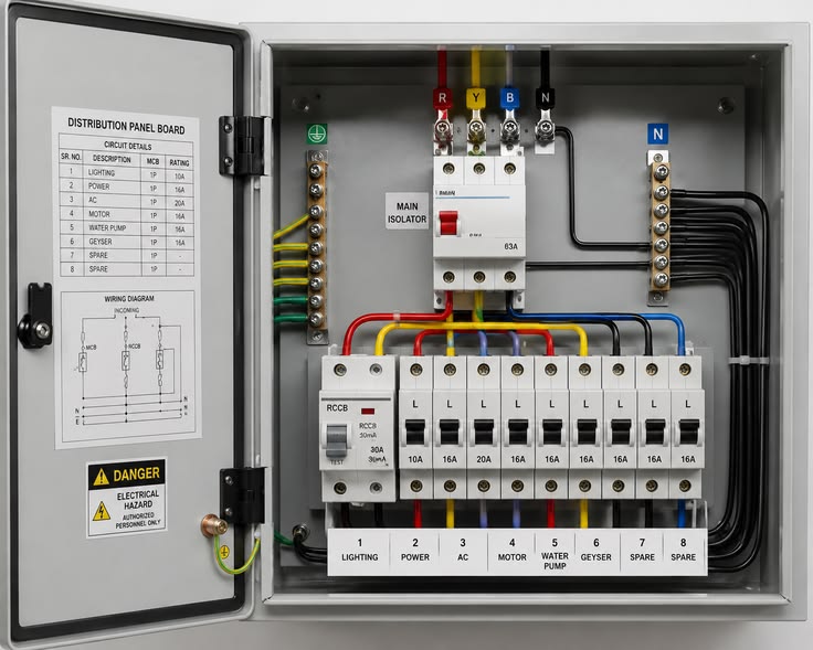
A pump is only as reliable as the panel that controls it. The pump control panel starts and stops the motor, watches for faults and shuts the pump down before damage occurs. Poor protection is one of the most common reasons motors burn out. This guide explains how pump control panels and motor protection work, what each component does, and how to choose the right arrangement for your pump.
What Does a Pump Control Panel Do?
A control panel has four main jobs:
- Switching: safely connecting and disconnecting the motor from the supply.
- Starting: limiting the surge of current when the motor starts.
- Protection: detecting overloads, short circuits, phase faults, dry running and other abnormal conditions.
- Control and monitoring: responding to level switches, pressure switches, timers or a PLC, and showing status and alarms.
In Kenya, the standard supply is 240 V single-phase or 415 V three-phase at 50 Hz, and the panel must be designed for the voltage and current of your motor.
Main Components Inside a Pump Panel
Incoming isolator or main breaker. Provides a visible way to disconnect the whole panel for maintenance.
Short-circuit protection (MCB, MCCB or fuses). These devices open instantly during a short circuit. They are sized to protect the cable and to allow the motor’s starting current without tripping.
Contactor. An electrically operated switch that connects the motor to power. It is rated for the motor current and for the number of starts expected.
Overload relay (thermal or electronic). Protects the motor from sustained overcurrent. Electronic overload relays can also detect phase loss and current imbalance.
Phase failure and phase sequence relay. Detects a missing phase, wrong phase order and voltage out of range. Running a three-phase motor on two phases overheats its windings rapidly.
Under- and over-voltage protection. Disconnects the pump when the supply voltage is outside its acceptable range, protecting against low-voltage burnouts common in weak networks.
Control circuit. A control transformer or supply, relays, selector switches (Hand/Off/Auto), indicator lamps and push-buttons.
Instrumentation inputs. Float switches, level probes, pressure switches or transmitters, and flow switches.
Surge protection. A surge protective device (SPD) limits damage from lightning and switching surges, an important feature on rural lines and boreholes.
Earth leakage protection. A residual current device (RCD) improves safety where people can touch pumps or pipes.
Enclosure. Sheet steel, stainless steel or plastic with an appropriate IP rating, such as IP54 for sheltered pump rooms and IP65 for outdoor or dusty locations. Panels need ventilation or cooling when containing drives or soft starters.
Starting Methods: Which One Do You Need?
When a motor starts across the line, it can draw about six to eight times its normal running current. Different starters manage this surge in different ways:
| Starter type | How it works | Best for | Limitations |
|---|---|---|---|
| Direct-on-line (DOL) | Connects the motor straight to the supply | Small pumps, strong supply | High inrush; water hammer; mechanical stress |
| Star-delta | Starts with windings in star (reduced voltage), then switches to delta | Medium three-phase motors with light starting load | Open transition can cause a current spike; needs six motor leads |
| Soft starter | Electronically ramps voltage up and down | Medium and large pumps; reduces water hammer | Runs at full speed after start; no speed control |
| Variable frequency drive (VFD) | Varies frequency and voltage | Variable demand, constant pressure, energy saving | Higher cost; harmonics; cable considerations |
For submersible borehole pumps, DOL starters are common for small single-phase units, while larger three-phase pumps benefit from soft starters or drives. Ask whether your electricity supplier limits starting current for your connection.
Motor Protection Explained
Overload protection. If a motor draws more than its rated current for too long, its windings overheat. Thermal or electronic overload relays follow an inverse-time curve: a small overload is tolerated for a long time, a large one trips quickly. The relay is set to the motor’s nameplate full-load current, adjusted for the service factor, and chosen with the appropriate trip class for the motor.
Short-circuit protection. Must clear a fault instantly, and be coordinated with the overload relay and the cable rating.
Phase loss and imbalance protection. A small voltage imbalance causes a much larger current imbalance, heating the motor. Phase protection is especially valuable on rural networks where single phases drop out.
Dry-run protection. Pumps rely on the pumped liquid for cooling and lubrication. Running dry damages seals and bearings in minutes, and burns out submersibles. Protection options include:
- Low-current or power-factor relays that detect the sudden fall in motor load when the pump loses water.
- Level probes or electrodes in the well or tank.
- Float switches that stop the pump at low water.
- Flow or pressure switches on the discharge side.
Temperature protection. Many motors have embedded thermistors (PTC) or resistance temperature detectors (such as PT100) in the windings, which a relay uses to trip the pump before insulation is damaged. This is the most direct form of thermal protection and is valuable on larger motors and in hot rooms.
Insulation monitoring. Periodic insulation resistance tests with a megohmmeter reveal moisture or ageing before a motor fails. Some panels include continuous insulation monitoring for critical pumps.
Locked rotor and stall protection. Detects a motor that cannot turn, for example due to a jammed impeller.
Water ingress and seal-leak sensors. Common in submersible sewage pumps, these warn of moisture in the motor housing before it causes a failure.
Control Modes and Automation
- Manual/Auto selection: Hand, Off and Auto switches let operators run the pump locally or from automatic controls.
- Level control: starts and stops pumps in sumps and tanks, with high and low alarms.
- Pressure control: pressure switches or transmitters for booster sets, with a VFD where constant pressure is needed.
- Duty/standby alternation: swaps lead and lag pumps to share wear, and starts the standby automatically on failure.
- Timers and clocks: schedule irrigation or pumping during off-peak electricity or sunny hours.
- PLC and SCADA: for larger sites, a programmable controller logs data, raises alarms and allows remote control.
- Remote monitoring: GSM or IoT modules send alarms and data to phones, valuable for remote boreholes.
Sizing a Pump Panel: Key Steps
- Gather motor data: voltage, full-load current, power in kW, starting method, service factor and insulation class.
- Select the starter based on motor size, supply capacity and the need to limit inrush.
- Size the short-circuit device and cables according to the motor current and electrical standards, allowing for voltage drop on long cable runs, a common issue with deep boreholes.
- Set the overload relay to the nameplate current, and choose the right trip class.
- Add the protections appropriate to the pump type: dry run for water pumps, seal-leak and temperature for sewage pumps, and surge protection for exposed sites.
- Choose the enclosure with a suitable IP rating and ventilation.
- Specify controls: level, pressure, alarms, alternation and any remote communication.
Panels should be built to recognised standards such as IEC 61439 for low-voltage switchgear assemblies, and components should conform to IEC 60947.
Installation and Safety Tips
- Install panels where they are dry, shaded, ventilated and accessible, away from direct water spray.
- Use correctly sized, well-terminated cables with proper glands, and tighten connections to specified torque.
- Label circuits, terminals and drawings, and keep a circuit diagram in the panel.
- Earth the panel and pump properly.
- Test protection functions at commissioning: simulate phase loss, low level and overload where safe to do so.
- Allow only qualified electricians to work on live panels, and use lock-out/tag-out when servicing.
Common Mistakes
- Setting the overload relay too high “to stop nuisance tripping”, leaving the motor unprotected.
- Omitting dry-run protection on borehole or sump pumps.
- Using undersized cable, causing voltage drop and overheating.
- No surge protection on exposed rural installations.
- Ignoring ventilation, causing drives and soft starters to overheat.
- Poor labelling and no drawings, making fault finding slow.
Conclusion
Pump control panels and motor protection safeguard the most expensive part of a pump set, its motor. The right starter, correctly set overload relay, phase and dry-run protection, and a sound enclosure and installation will prevent most electrical failures. Specify the panel for the pump and site, test every protection at commissioning, and maintain it as carefully as the pump itself.
Sources and Further Reading
- International Electrotechnical Commission, IEC 61439 (low-voltage switchgear and controlgear assemblies) and IEC 60947 (low-voltage switchgear and controlgear): iec.ch
- Hydraulic Institute, pump system resources: pumps.org
- Energy and Petroleum Regulatory Authority (EPRA), Kenya electrical installation licensing: epra.go.ke
- Kenya Bureau of Standards (KEBS): kebs.org
