
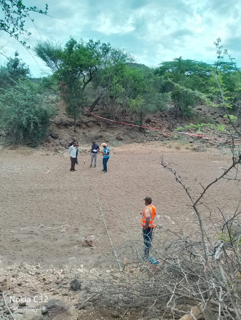
A road is only as strong as the ground beneath it. The subgrade, the natural or compacted soil that supports the pavement layers, carries every wheel load that passes over the road. If it is weak, wet or expansive, even a well-built surface will crack, rut and break up within a few years. That is why subgrade testing is the first step in pavement design. This article explains how the subgrade is tested, how California Bearing Ratio (CBR) results are used, and what to do when the subgrade is poor.
What Is the Subgrade and Why Does It Matter?
A typical flexible pavement has a surfacing (asphalt or surface dressing), a base course, a subbase, and then the subgrade. Each layer spreads the load over a wider area, so stresses on the subgrade are much lower than at the surface. Yet the subgrade is usually the weakest layer, and its stiffness and strength determine how thick the upper layers need to be. A weak subgrade means a thicker, costlier pavement. A strong subgrade allows thinner, cheaper designs.
Subgrade behaviour is also strongly affected by moisture. Many clays lose half or more of their strength when soaked, and expansive soils swell and shrink, deforming the pavement. Good drainage and moisture control are therefore as important as strength.
Planning the Subgrade Investigation
A road investigation should reflect the length and variability of the route. Common practice includes:
- Desk study: geology maps, soil maps, drainage, existing road performance, and borrow source information.
- Test pits or auger holes at regular intervals, commonly every 250 to 500 m for new roads, and closer where soil changes. Depths of at least 1.0 to 1.5 m below formation level are typical, and deeper where soft soils or cuts are expected.
- Soil profiling and logging to identify changes in soil type along the road.
- Sampling for laboratory testing from each distinct soil type, not just every fixed distance.
- Groundwater and drainage observations, including seasonal flooding and the depth of water table relative to formation level.
Dividing the road into homogeneous sections with similar soil and strength is a key step. Each section is then designed with its own representative CBR.
Laboratory Tests on Subgrade Soils
Classification tests: particle size distribution and Atterberg limits (liquid limit, plastic limit, plasticity index) classify the soil using systems such as AASHTO or USCS. High plasticity and a high percentage of fines warn of poor behaviour.
Compaction tests: Proctor tests (standard or modified) provide Maximum Dry Density (MDD) and Optimum Moisture Content (OMC), used to specify and control field compaction, commonly to 93 to 100% of MDD depending on layer and standard.
California Bearing Ratio (CBR): the main strength test, described below.
Swell and shrinkage tests: measured during the soaked CBR test and by free-swell or linear shrinkage tests for expansive soils.
Chemical tests: where relevant (for example, sulphate content before using cement or lime stabilisation).
The California Bearing Ratio (CBR) Test
The CBR test (BS 1377 Part 4, ASTM D1883, AASHTO T193) measures the resistance of a compacted soil sample to penetration by a standard plunger and expresses it as a percentage of the resistance of a standard crushed stone.
Procedure in brief:
- A soil sample is compacted in a 152 mm diameter mould at a specified moisture content and density, often at OMC and 95 to 100% of MDD (or at several densities).
- The sample is soaked for four days under a surcharge representing pavement weight, and swell is recorded. Soaking simulates the worst moisture condition. In areas with deep water tables and little rainfall, an unsoaked or partly soaked condition may be justified by design guidance.
- A 50 mm diameter plunger is pushed into the sample at 1.25 mm per minute, and the load is recorded at penetrations up to 7.5 mm.
- CBR = (test load / standard load) × 100, at 2.5 mm and 5.0 mm penetration. The standard loads are about 13.2 kN at 2.5 mm and 20 kN at 5.0 mm. The higher value is usually reported if the 5.0 mm value is higher and the result is confirmed by retest.
Typical soaked CBR values: soft plastic clays and black cotton soils 1 to 3%, silty clays 3 to 8%, sandy clays and gravelly clays 8 to 25%, good gravels and weathered rock 25 to 80%, and crushed stone bases above 80%.
Representative design CBR. Because soils vary, designers do not use the lowest or average value blindly. Common practice is to use a design percentile, for example the 10th to 20th percentile of results (so that most test values exceed it) for each homogeneous section, or the 90th percentile of reduced values. Standards and national road manuals specify the approach.
Subgrade Classes
Road design manuals group subgrades into classes by CBR to simplify design. For example, TRL Overseas Road Note 31 and the Kenya Road Design Manual use a series of classes (S1 to S6) from very weak subgrades with CBR of about 2 to 5% up to strong subgrades above about 30%. Each class is linked to pavement thickness charts together with design traffic (measured in million standard axles). Always use the current national manual for the project.
In-Situ Testing: DCP and Others
Dynamic Cone Penetrometer (DCP) (ASTM D6951). A steel cone is driven into the ground by a standard weight (typically 8 kg dropped 575 mm), and penetration per blow (mm per blow) is recorded with depth. The DCP is fast, cheap and gives a continuous strength profile down to about 800 mm to 1 m. Correlations such as CBR = 292 / DCPI^1.12 (with DCPI in mm per blow) are widely used for soils, though they should be checked for local soils. DCP is invaluable for checking subgrade uniformity, identifying weak layers and assessing existing roads for rehabilitation.
Plate load test (ASTM D1196). A loaded steel plate yields the modulus of subgrade reaction (k value) used for rigid (concrete) pavements.
Falling Weight Deflectometer (FWD) and Benkelman beam tests measure deflection of existing pavements to back-calculate layer stiffness for overlay design.
Field density tests (sand replacement, nuclear density gauge) verify compaction on site.
From CBR to Resilient Modulus
Modern mechanistic design methods (such as AASHTO 1993 and the Mechanistic-Empirical Pavement Design Guide) use resilient modulus (Mr), the stiffness under repeated loading, rather than CBR. Because direct testing is expensive, correlations are commonly used. A common one is Mr (MPa) ≈ 17.6 × CBR^0.64 (for CBR between 2 and 12%), while another popular approximation is Mr (MPa) ≈ 10 × CBR. These are rough relationships and should be used with caution.
How CBR Controls Pavement Design
Pavement thickness charts and equations take subgrade strength and traffic as the main inputs. A low CBR results in significantly thicker pavement layers. For example, in a typical design, raising subgrade CBR from 3% to 15% can reduce the total thickness of granular layers by several hundred millimetres, with a major effect on cost per kilometre. This is why subgrade improvement can pay off.
Dealing with Weak and Problematic Subgrades
1. Improve compaction and drainage. Compacting the top 150 to 300 mm of subgrade to a high density can significantly increase CBR. Side drains, mitre drains and subsurface drainage keep the subgrade dry.
2. Capping layer or select fill. Placing a layer of better material (for example, gravel or crushed rock with CBR above 15 to 30%) over weak soils spreads load and protects the subgrade during construction.
3. Chemical stabilisation. Lime (typically 2 to 8%) is effective for plastic clays, including black cotton soil, reducing plasticity and swell and raising CBR from single digits to 15 to 40% or more with curing. Cement (typically 3 to 8%) suits sandy and low-plasticity soils. Mix design with UCS and CBR testing is needed, along with attention to sulphates and organic matter.
4. Removal and replacement. Excavate and replace very soft or expansive soil to a depth of 0.5 to 1.5 m or more, using compacted granular fill.
5. Geosynthetics. Geotextiles for separation and geogrids for reinforcement reduce required thickness over soft subgrades.
6. Moisture control for expansive soils. Wide shoulders, sealed shoulders, vertical moisture barriers and good drainage reduce seasonal moisture variation at the edges of the road, where most distress starts.
Common Mistakes to Avoid
- Using a single CBR for a whole route with varying soils.
- Testing at the wrong density or moisture condition, which overstates the strength.
- Ignoring seasonal moisture, so that the road performs well in the dry season but fails in the rains.
- Poor drainage design.
- Ignoring swell in the CBR test results.
- Skipping quality control during construction, such as density checks and DCP checks of subgrade after compaction.
Conclusion
Subgrade testing and CBR are the foundation of sound pavement design. A well-planned investigation, correct laboratory testing at design density and moisture, in-situ checks with the DCP and a sensible choice of design CBR for each homogeneous section allow engineers to select economical pavement thicknesses and to decide when improvement is worthwhile. Combined with good drainage and construction control, these steps give roads that last longer and cost less to maintain.
References and further reading
- TRL (1993). Overseas Road Note 31: A guide to the structural design of bitumen-surfaced roads in tropical and sub-tropical countries
- Ministry of Roads (Kenya), Road Design Manual Part III: Materials and Pavement Design for New Roads
- AASHTO (1993). Guide for Design of Pavement Structures
- BS 1377-4:1990; ASTM D1883; ASTM D6951
- Powell, W.D. et al. (1984). The structural design of bituminous roads. TRRL Report LR1132
- Huang, Y.H. Pavement Analysis and Design
