
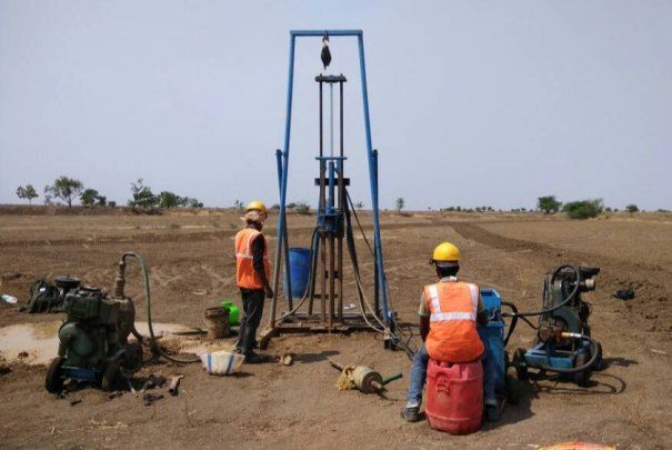
Excavate below the water table and the ground fills with water. Left uncontrolled, groundwater turns a pit into a pond, destabilises excavation walls, softens the base and can even lift the floor of the excavation. Dewatering, the controlled removal or exclusion of groundwater, keeps construction sites safe and dry. But it also carries risks, from settlement of neighbouring buildings to environmental damage. This article explains how groundwater behaves, the main dewatering methods, and how to manage the risks.
How Groundwater Behaves
Below the water table, soil pores are filled with water. Water flows from areas of high hydraulic head to low head, at a rate governed by Darcy’s law:
Q = k · i · A
where Q is flow rate, k is the hydraulic conductivity (permeability) of the soil, i is the hydraulic gradient and A is the flow area. Permeability varies enormously between soils. Typical values are about 10⁻² to 10⁻³ m/s for clean gravel, 10⁻³ to 10⁻⁵ m/s for sand, 10⁻⁵ to 10⁻⁸ m/s for silty sand and silt, and less than 10⁻⁹ m/s for clay. This variation largely determines which dewatering method will work.
Groundwater may be unconfined (a free water table) or confined (trapped under pressure beneath a less permeable layer such as clay), where artesian pressures can lift the base of an excavation if not controlled. Perched water tables, tidal influence, river connections and seasonal fluctuations all complicate behaviour, so groundwater levels should be monitored over time, ideally through at least one wet season, with standpipes or piezometers installed during site investigation.
Why Dewatering Is Needed
Dewatering is used to:
- Keep excavations dry for foundations, basements, trenches, tunnels and shafts.
- Maintain stable excavation sides and bases.
- Prevent piping and boiling, where upward seepage carries soil into the excavation.
- Control uplift pressure on the base of excavations.
- Allow concrete placement and compaction in dry conditions.
- Reduce water pressure on retaining walls and temporary supports.
Site Investigation for Dewatering
Good design relies on good data: borehole logs showing soil layers, particle size analysis, groundwater levels and fluctuations, permeability from pumping tests, packer tests, falling-head tests or grading correlations, and information on nearby water sources, wells, rivers and structures. A pumping test (pumping from a test well while measuring drawdown in observation wells) is the most reliable method to measure aquifer properties, and is particularly valuable on large or critical projects.
Main Dewatering and Groundwater Control Methods
1. Open sumps and ditches. Water seeps into the excavation and is collected in sumps or ditches, then pumped away. This is the simplest and cheapest method and is suitable for shallow excavations in clays, silts and tight soils, or in coarse gravels at low flow rates. Limitations: in fine sands and silts, upward seepage can cause loss of fines, instability and boiling. Open pumping may also cause erosion of excavation faces and is poorly suited to deep excavations in permeable ground.
2. Wellpoints. Closely spaced small-diameter wells (typically 1.5 to 3 m centres) are jetted or drilled around the excavation and connected by a header pipe to a vacuum pump. Wellpoints are suited to sands and silty sands. A single stage can lower the water table by about 4 to 6 m (limited by suction lift), and deeper drawdown requires multiple stages in tiers. They are quick to install and good for trenches and linear works, but they require continuous pumping and fuel, and they are less effective in coarse gravels (too much flow) or clays (too slow).
3. Deep wells. Larger-diameter bored wells with submersible pumps are installed at wider spacing around or inside the excavation. They are used for deep excavations and high flow rates in permeable soils such as sand and gravel, and can lower water levels by tens of metres. They typically need less intensive pipework than wellpoints but involve higher cost per well.
4. Ejector wells. Using a venturi system powered by high-pressure water, ejectors can draw water from deeper levels and work in lower-permeability soils such as silty sands, where wellpoints and deep wells are less efficient.
5. Cut-off walls. Instead of removing groundwater, a barrier is built to block flow. Options include steel sheet piles, diaphragm walls, secant or contiguous piles, slurry walls, jet grouting, and deep soil mixing. A cut-off can reduce pumping volumes and limit drawdown outside the site, but it must penetrate into a low-permeability layer to be effective, and leaks at joints or toe must be controlled. Often cut-offs are combined with limited internal pumping.
6. Ground freezing. Circulating a coolant through pipes in the ground freezes the pore water, forming a strong, impermeable barrier. It is used for shafts, tunnels, and special projects in difficult ground, but it is expensive and slow to establish.
7. Grouting. Injecting cement or chemical grout fills voids and reduces permeability, useful for local seepage control and around structures.
8. Recharge systems. Water pumped from dewatering can be returned to the ground through recharge wells or trenches outside the site to maintain groundwater levels near sensitive structures, limiting settlement and impact on wells.
Choosing a Method
The right method depends on soil permeability, depth of excavation, required drawdown, site constraints, duration, environmental sensitivity, and cost. A rough guide:
| Soil type | Typical permeability (m/s) | Suitable methods |
|---|---|---|
| Clean gravel | above 10⁻³ | Deep wells, cut-off walls, sumps (with high pumping) |
| Sand | 10⁻³ to 10⁻⁵ | Wellpoints, deep wells |
| Silty sand, silt | 10⁻⁵ to 10⁻⁷ | Ejector wells, vacuum wellpoints, cut-offs |
| Clay | below 10⁻⁸ | Sumps, usually little dewatering needed |
| Fractured rock | variable | Deep wells, grouting, cut-offs |
Dewatering is often combined with excavation support and temporary works design, as groundwater pressure is a major load on walls and props.
Estimating Pumping Rates and Radius of Influence
Designers use analytical methods such as well formulae for steady-state flow, or numerical groundwater models for complex sites. A common empirical formula for radius of influence in unconfined aquifers is Sichardt’s equation: R ≈ 3000 · s · √k, with s the drawdown in metres, k in m/s and R in metres. This gives a rough estimate, used for preliminary design only. Field pumping tests and monitoring are essential for reliable results.
Risks of Dewatering
Dewatering is not risk-free. The main hazards include:
1. Settlement of adjacent structures. Lowering the water table increases effective stress in the soil (since the buoyant support from water is removed), so the ground compresses. Soft clays, peats and loose fills can settle significantly over a wide area, damaging nearby buildings, roads and services. Settlement can occur at distances well beyond the excavation, depending on drawdown and soil.
2. Piping, boiling and loss of ground. Upward seepage can reach a critical hydraulic gradient (approximately 1 in cohesionless soil) at which effective stress becomes zero, and the soil behaves like a liquid. Fine sand and silt can be carried into wells or sumps, leaving voids and settlement. Poorly designed wells or filters that pump fines are a warning sign.
3. Base heave and uplift failure. Where a low-permeability layer such as clay overlies a confined, pressurised aquifer, the water pressure beneath the layer may exceed the weight of soil above, lifting the excavation base. The check is simple: compare the weight of soil above the aquifer with water pressure below, with an adequate factor of safety (often 1.1 to 1.2 or more depending on code). Relief wells or pressure reduction are needed to avoid this.
4. Instability of excavation walls. Seepage forces reduce the stability of slopes and retaining systems. Dewatering ahead of excavation usually improves stability, but poorly managed pumping can create erosion or localised failures.
5. Impact on nearby wells, springs and water resources. Drawdown can dry out neighbours’ boreholes or damage ecosystems such as wetlands.
6. Saline or contaminated water. In coastal areas, over-pumping can draw saltwater inland. In contaminated sites, pumping may spread pollution, and discharge needs treatment.
7. Discharge and environmental issues. Pumped water often contains sediment and may require settling tanks, treatment and permits before discharge. Uncontrolled discharge can cause erosion, flooding, or water-quality problems.
8. Regulatory and legal exposure. In many countries, abstraction and discharge of groundwater need permits. In Kenya, the Water Resources Authority regulates groundwater abstraction, so contractors should check the permit requirements early.
9. Operational risks. Pump failure, power cuts, and fuel shortages can cause rapid flooding or loss of stability. Standby pumps and generators are essential. Sudden switch-off of dewatering during construction can also cause uplift of partly completed structures, so the dewatering schedule must account for the structural weight needed to resist buoyancy.
Managing the Risks
- Investigate thoroughly and plan with groundwater models for large or sensitive sites.
- Install monitoring: observation wells and piezometers inside and outside the site, settlement markers on adjacent structures, flow meters and turbidity checks on discharge.
- Set trigger levels (for example, maximum drawdown, settlement limits) with agreed action plans if exceeded.
- Use cut-offs and recharge where drawdown must be limited near sensitive structures.
- Use properly designed filters and screens to prevent pumping of fines.
- Provide redundancy: standby pumps, power and trained operators, with 24-hour monitoring on critical works.
- Phase dewatering carefully, lowering levels gradually to avoid sudden changes in stress.
- Manage discharge: use settlement tanks, obtain permits, and avoid affecting neighbours or watercourses.
- Plan the end of dewatering: switch off only when the structure has enough weight, or tie-down, to resist uplift.
Conclusion
Groundwater control is one of the most important and most underestimated parts of excavation work. The right dewatering method depends on soil permeability, excavation depth and surroundings, and success depends on solid investigation, careful design and active monitoring. By understanding the risks of settlement, piping, uplift and environmental impact, and by managing them with cut-offs, recharge, monitoring and contingency plans, engineers can keep excavations dry and stable without harming neighbours or the environment.
References and further reading
- Powers, J.P., Corwin, A.B., Schmall, P.C., Kaeck, W.E. Construction Dewatering and Groundwater Control (3rd ed.)
- Preene, M., Roberts, T.O.L., Powrie, W., Dyer, M.R. Groundwater Control: Design and Practice, CIRIA C515
- Cashman, P.M. and Preene, M. Groundwater Lowering in Construction: A Practical Guide
- Sichardt, W. and Kyrieleis, W. (1930). Grundwasserabsenkungen bei Fundierungsarbeiten
- EN 1997-1, Eurocode 7: hydraulic failure checks (uplift, heave, internal erosion, piping)
- Water Resources Authority (Kenya), groundwater abstraction permitting guidelines
