
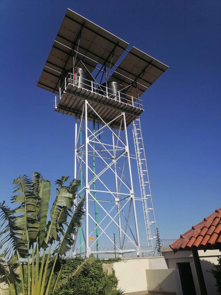
Steel towers are the quiet backbone of modern infrastructure. They carry the antennas that keep mobile networks connected, the conductors that move electricity from power stations to cities, the floodlights that light stadiums and ports, and the sensors that monitor wind and weather. In East Africa, where mobile coverage, rural electrification and geothermal power are expanding fast, demand for well-designed towers keeps growing. This guide explains what steel towers are, the main types, how they are designed, and how they move from drawing board to completed structure.
What Is a Steel Tower?
A steel tower is a tall, slender structure made from rolled steel sections or tubes that supports equipment well above the ground. Steel is the preferred material because of its high strength-to-weight ratio, predictable behaviour, ease of fabrication and the ability to be galvanized for decades of service. Typical heights range from 15 m for small rooftop or community masts to more than 100 m for broadcast towers and long-span transmission crossings.
Every tower has one basic job: carry loads safely to the ground. Those loads include the self-weight of the steel, the weight of equipment, wind pressure, ice or rime where relevant, and the forces created during construction and maintenance. Wind is almost always the controlling load because towers are tall, light and exposed.
Main Types of Steel Towers
Lattice (angle or tubular) towers are built from steel angles or tubes arranged in a braced framework, usually with three or four legs. They are efficient, stiff and cost-effective at heights above about 30 m. They need a larger footprint but use less steel per metre than solid shafts.
Monopoles are single tapered tubular shafts, often 12-sided, 16-sided or round. They have a small footprint, a clean appearance and are favoured in urban and visually sensitive locations.
Guyed masts are slender vertical masts stabilised by steel guy wires anchored to the ground at several levels. They are the lightest and cheapest way of reaching very great heights, but they require a large land area.
Transmission towers carry overhead power lines. They are lattice structures designed for conductor tension, wind on conductors and the possibility of broken wires.
Specialised towers include rooftop masts, camouflage (tree, flagpole or chimney) structures, floodlight masts and meteorological towers.
Design Fundamentals
Tower design starts with a clear brief: height, equipment to be carried now and in the future, site conditions and the required lifespan, typically 25 to 50 years. Engineers then apply a design standard such as ANSI/TIA-222 (widely used for communication structures), Eurocode EN 1993-3-1 for towers and masts, IEC 60826 or ASCE 10 for transmission structures, and local building regulations.
The key steps are:
- Define loads. Dead load, equipment load, wind load, ice load where relevant, seismic load and construction or maintenance loads such as climbers and hoists.
- Combine loads. Standards specify load factors and combinations so that the structure is checked against the worst realistic scenarios.
- Analyse the structure. Modern design uses 3D finite-element software to model members, joints and the effect of deflection on forces.
- Check members and connections. Each leg, brace, plate and bolt group is verified for tension, compression, bending, buckling and bearing.
- Check serviceability. Antennas for microwave links, for example, need limited twist and sway so the beam does not drift out of alignment.
- Design foundations. Soil bearing, uplift and overturning are checked using site-specific geotechnical data.
Wind: The Governing Load
Wind pressure rises with height and depends on terrain roughness, local topography, gust response and the shape of the tower. A tower on an open Rift Valley escarpment will experience more severe wind than the same tower in a sheltered urban basin. Standards convert a basic wind speed into design pressure using factors for exposure, height and gust effects, and then multiply by the exposed area and a force coefficient that reflects the tower’s shape and solidity.
Equipment matters. A dense array of dishes and panel antennas can increase wind area by a large margin, which is why a tower that was adequate five years ago may be overloaded today. This is explored further in the articles on wind load calculation and structural audits.
Foundations and Geotechnics
A tower is only as reliable as the ground that supports it. Foundations resist compression, uplift, overturning and sliding. Common options include pad-and-chimney footings, piles, drilled shafts, raft foundations and rock anchors. The choice depends on soil strength, groundwater level, rock depth and the magnitude of loads.
In Kenya, expansive black cotton soils, soft lake sediments, loose volcanic ash and shallow fractured rock all occur within short distances. A geotechnical investigation with boreholes and in-situ tests should precede detailed foundation design. Skipping it is a false economy: the foundation is usually the most expensive element to correct after construction.
Materials and Corrosion Protection
Most tower steel is structural grade such as S355 or ASTM A572 Grade 50 for main members, with S275 or A36 for secondary parts. Bolts are typically grade 8.8 (ISO 898-1) or ASTM A325 and A394 equivalents. All parts should be hot-dip galvanized to ISO 1461 or ASTM A123, which gives a zinc coating that protects steel from corrosion for decades in most inland environments. Coastal sites near Mombasa need thicker coatings, or an additional paint system, because chloride accelerates corrosion.
From Fabrication to Erection
After design approval, detail drawings are produced for every member. Steel is cut, drilled or punched, welded where needed, and galvanized. Quality control includes material certificates, weld inspection, dimensional checks and coating thickness measurements. Components are then trial-assembled in the workshop for complex towers, marked, packed and transported to the site.
On site, the sequence is: set out and excavate; install anchor bolts or stubs; cast and cure concrete; erect the tower by crane, gin-pole or section-by-section assembly; tension guys where applicable; tighten bolts to specified torque; install antennas, cables, lighting and earthing; and complete a final inspection. Each stage requires planning, particularly for safe work at height.
Lightning, Lighting and Access
Because towers are the tallest objects in their surroundings, they attract lightning. A proper earthing system, air terminals and surge protection protect people, equipment and the structure. Taller structures may require aviation obstruction lighting and painting under Civil Aviation rules. Climbing facilities, rest platforms, fall-arrest systems and cable ladders must be designed into the tower rather than added later.
Costs and Lifecycle Thinking
The purchase price of a tower is only part of the story. Steel weight, height, wind zone, foundation type, access and logistics all influence cost, as does the design life. Spending a little more on thicker galvanizing, better connection details and design allowance for future antennas usually reduces the lifetime cost. The dedicated article on price per metre explains the cost drivers in detail.
Inspection, Maintenance and Upgrades
A tower does not stop needing attention once it is built. Periodic inspections check bolt tightness, coating condition, corrosion, deformation, foundation condition, guy tension and lighting. Any new antenna or dish should trigger a structural re-check. Regular maintenance extends the working life and prevents sudden failures.
Regulation and Approvals
In Kenya, tower projects typically involve county planning approval, environmental assessment under NEMA, aviation clearance from the Kenya Civil Aviation Authority for taller structures, and, for telecom, coordination with the Communications Authority. Power line towers involve wayleave processes and utility approvals. Working with an experienced consultant early prevents delays.
Conclusion
Steel towers look simple from the ground, but each one is the product of careful decisions about loading, geotechnics, materials, fabrication and safety. Choosing the right type, designing to recognised standards, protecting steel against corrosion and maintaining the structure through its life are the keys to a reliable tower. Whether you are planning a new telecom site or assessing an existing structure, begin with sound site data and a clear brief, and involve qualified structural and geotechnical engineers from the start.
Key references: ANSI/TIA-222-H; EN 1993-3-1; EN 1991-1-4; IEC 60826; ASCE 10; ISO 1461; ASTM A123.
