
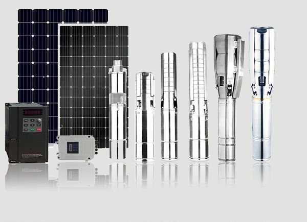
A borehole can be a reliable lifetime source of water, but only if the pump is selected and installed correctly. Installing a pump in a borehole is very different from installing one on the surface. The equipment is hidden underground, access for repairs is difficult, and mistakes, such as setting the pump too deep, dropping the unit, or running it dry, are expensive. Following a disciplined, step-by-step process protects the borehole, the pump, and your investment.
This guide walks through the full procedure for installing a submersible borehole pump, from preparation to commissioning, with the safety and quality checks that professionals use.
Before You Start: Information You Need
Good installation depends on good data. Gather the following before choosing or lowering any equipment:
- Borehole completion records: depth, diameter, casing and screen positions, and construction date.
- Pumping test results: static water level, pumping water level at the tested rate, drawdown, and the safe yield or recommended pumping rate.
- Water quality: presence of sand, iron, corrosive or saline water, which affects material choice and pump life.
- Verticality and clearance: a borehole that is bent or has a reduced internal diameter can stop a pump from passing.
- Demand and delivery details: required flow rate, delivery point, storage tank elevation, and pipe route.
Without a pumping test, selecting a pump is guesswork, and pumping beyond the safe yield can draw down the well, pull in sand, and destroy the pump.
Step 1: Select the Pump and Components
Calculate flow and head. Determine the required flow rate within the safe yield of the borehole. Then calculate total dynamic head using the pumping water level, not the resting level, plus delivery height, friction losses, and any required pressure.
Choose the pump. Select a multistage submersible pump whose best efficiency point is close to your duty. Confirm that the pump and motor diameter fit comfortably inside the casing, leaving room for water to flow past the motor for cooling.
Choose the motor. Match the motor to the pump’s power demand and the electrical supply, whether single-phase or three-phase. Check cable sizing and starting method.
Select the rising main. Options include galvanised steel, HDPE, uPVC or flexible layflat hose, depending on depth, pressure and cost. Rigid pipe with proper threaded or flanged joints is typical for deep installations. Check pipe pressure rating against the maximum head and any surge pressures.
Select cable and accessories. Use a submersible cable rated for the motor current and voltage drop limits. You will also need cable clips or tape, a safety rope or cable, a non-return valve at the pump or at intervals, a sanitary well seal or cap, and level sensors or protection devices.
Choose control and protection. Include a starter or variable speed drive, overload protection, phase failure protection, and dry-run protection, such as a level probe or current-sensing relay.
Step 2: Prepare the Site and Borehole
Clear and secure the area. Provide space for the rig, tripod or crane, pipes and equipment. Keep the area clean to prevent dirt falling into the borehole.
Check the borehole. Measure the total depth with a weighted line and confirm the static water level with a dip meter. If the depth has reduced from the completion record, sediment or collapse may have occurred, and cleaning or development may be needed before installation.
Verify the casing diameter and clear passage. Lower a dummy pipe or gauge slightly longer than the pump to confirm there is no obstruction or bend.
Disinfect equipment. Clean the pump, pipe, and cable before installation. For potable supplies, disinfect with chlorine solution as part of good hygiene practice, and follow local water authority guidelines.
Plan the pump setting depth. Position the pump well below the lowest expected pumping water level, with sufficient submergence above the pump intake. A common practice is to keep the pump at least several metres below the dynamic water level at the design rate, and above the top of the screen or the borehole bottom, avoiding sediment and ensuring adequate cooling flow past the motor. Follow the manufacturer’s minimum submergence and minimum flow-past-motor requirements.
Step 3: Check the Equipment
Before lowering anything, check that:
- Pump and motor nameplates match the specification.
- The pump shaft turns freely by hand.
- The motor is filled with the correct fluid, where applicable, and the shaft seal is intact.
- The motor winding and cable insulation pass an insulation resistance test using a megohmmeter. Record the reading as a baseline.
- The motor rotation direction is correct for the pump. For three-phase units, this can be checked briefly in a safe, wet condition per manufacturer guidance, or by testing flow after installation and swapping two phases if the output is low.
- All threaded or flanged connections are clean and undamaged.
Step 4: Assemble and Lower the Pump
Connect the pump and motor, following torque specifications. Install the motor cable guard, if provided, to protect the cable at the pump.
Attach the first pipe section and the non-return valve. Many installers fit a non-return valve directly above the pump, with additional valves at intervals in deep installations to limit water hammer and reduce reverse flow loads.
Secure the safety rope. Attach a stainless steel wire or polypropylene rope to the pump’s lifting eyes and tie it off at the surface. This provides a lifeline if a pipe joint fails and allows easier retrieval. Do not rely on the electrical cable for support.
Lower the pump gradually. Use a tripod, gantry or crane. Add each pipe section, tighten joints properly, and use thread sealant or PTFE tape as appropriate. Secure the cable to the pipe with clips or tape every 2 to 3 metres, avoiding sharp bends and abrasion on the casing edges.
Avoid damage. Never drop the pump, drag the cable over sharp edges, or allow the cable to twist and kink. Protect the cable from being pinched between the pipe and casing.
Maintain vertical alignment. Keep the assembly centred and avoid pushing it against the casing walls. Take care when installing in boreholes with slight bends.
Install any level probes or monitoring cables at the correct depths, securing them to the rising main.
Step 5: Set the Pump at Depth and Fit the Well Head
When the pump reaches the planned depth, support the rising main using a pipe clamp or flange arrangement at the wellhead. The assembly should hang freely and be supported at the surface, not resting on the pump.
Install the wellhead. Fit a sanitary well cap or seal that prevents contamination from surface water, insects, and debris. Provide a cable gland or sealed entry for the electrical cable, a vent that is screened, and a port for water level measurements.
Fit a sampling tap, pressure gauge and air release valve on the surface pipework. Include a flow meter if measuring abstraction, which is increasingly required by water regulators in many regions.
Make the surface connection with flexible couplings or expansion allowances where needed, and support the pipework independently.
Step 6: Connect Electrical Supply and Controls
Electrical work should be carried out by a competent electrician.
- Splice the cable: use a certified waterproof splice kit for joining motor and supply cables, and test insulation after jointing.
- Install the control panel: locate it in a protected, ventilated, and accessible place, with a lockable enclosure.
- Set protection: configure overload, phase failure, under-voltage and over-voltage, and dry-run protection according to the motor data.
- Provide earthing: earth the pump, pipework, wellhead and panel to the electrical earth system.
- Surge protection: in lightning-prone regions, install surge arresters at the panel, as borehole pumps are vulnerable to induced surges.
- Wire any level control such as float switches, probes or pressure transducers.
If using a solar or generator supply, check that the supply capacity and starting characteristics suit the motor.
Step 7: Commissioning and Testing
Commissioning proves that the installation performs as designed and sets baseline values.
- Flush the borehole and pipework. Start the pump with the discharge valve partly open and run to waste until the water is clear of sand and debris. Do not run into storage until the water is clean.
- Check rotation and flow. Confirm correct direction by comparing flow and pressure to the pump curve. Low flow or unusual noise can indicate reverse rotation.
- Open the discharge valve gradually until the design flow is reached. Avoid running at very low flow or against a closed valve.
- Measure performance. Record flow rate, discharge pressure, voltage, current per phase, power, and water level while pumping.
- Check for sand pumping. Persistent sand indicates borehole or screen problems, or too high a pumping rate. Reduce flow and investigate.
- Monitor drawdown. Compare actual pumping water level with the design assumption. If drawdown is higher than expected, reduce flow or review the pump setting.
- Verify protection devices. Test dry-run protection and overload settings.
- Check for leaks and vibration on surface pipework and wellhead.
- Disinfect the system for potable supply and take water samples for testing if required.
- Record all values as a baseline for future maintenance and troubleshooting.
Step 8: Handover and Documentation
A professional installation ends with documentation:
- Pump model, serial numbers, and specifications
- Setting depth, pipe lengths and materials
- Cable type and length
- Static and pumping water levels, flow rates and test results
- Electrical settings and protection configuration
- Water quality results
- Operation and maintenance instructions and warranty details
- Safe yield and recommended maximum pumping rate
Provide the owner or operator with a brief training session covering normal operation, warning signs, and what to do if something goes wrong.
Common Installation Mistakes
- Setting the pump too shallow, causing air entrainment, cavitation, and dry running when the water level drops.
- Setting the pump too deep, into sediment at the borehole bottom.
- Pumping above the safe yield, draining the well and drawing in sand.
- Using the resting water level to calculate head.
- Ignoring motor cooling requirements, especially in wide casings where water bypasses the motor without flowing past it. A flow sleeve can solve this.
- Supporting the pump by the cable or using weak rope.
- Poor cable joints that leak and cause insulation failure.
- No non-return valve, leading to reverse flow, upthrust, and damage.
- Lack of surge protection in lightning-prone areas.
- Skipping commissioning measurements and baseline documentation.
Maintenance Tips After Installation
- Monitor flow, pressure, current, and water level regularly.
- Watch for gradual changes, such as falling flow, rising current, or increasing sand content.
- Check wellhead seals and cable glands periodically.
- Test insulation resistance of the motor and cable at intervals.
- Keep spare parts such as control components, fuses and seals available.
- Plan pump removal and inspection at intervals recommended by the manufacturer or when performance declines.
- Keep the area around the wellhead clean, secure and well drained.
Conclusion
A successful borehole pump installation rests on accurate data, correct equipment selection, careful lowering, clean and protected wellhead arrangements, proper electrical protection and thorough commissioning. Use the pumping test to set the flow rate, calculate head from the pumping water level, set the pump at a safe depth, support it with a safety rope, protect the borehole from contamination, and record every measurement. Follow these steps, and your borehole pump will deliver clean, reliable water for many years with minimal intervention.
