
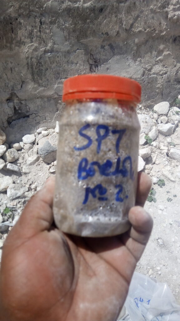
Every electrical installation needs a safe path for fault and lightning currents to reach the ground. That path is the earthing (grounding) system, and its performance depends largely on one property of the soil: resistivity. Rocky, dry ground can make a good earth very hard to achieve, while moist clay can make it easy. Measuring soil resistivity before design saves money, avoids over-design or under-design and keeps people and equipment safe. This article explains what soil resistivity is, how it is measured, how to use the results, and how to improve poor ground.
What Is Soil Resistivity?
Soil resistivity (ρ) is a measure of how strongly the soil resists the flow of electric current. It is expressed in ohm-metres (Ω·m) and represents the resistance between opposite faces of a one-metre cube of soil. Lower resistivity means better conduction and easier earthing.
In soil, current flows mainly through moisture and dissolved salts in the pores, not through the mineral grains. Therefore, resistivity depends mostly on:
- Moisture content: wetter soil conducts much better, and resistivity rises sharply when soil dries below about 15 to 20% moisture.
- Salt and mineral content: dissolved salts and conductive minerals (such as clays) reduce resistivity.
- Temperature: resistivity increases as temperature drops, rising sharply near and below freezing.
- Soil type and compaction: clays hold water and generally have low resistivity, while sand, gravel and rock have high resistivity.
- Layering: most sites have layers with different resistivities, such as dry sand over wet clay.
Because moisture changes with season, resistivity varies throughout the year. Dry-season values are usually the worst case, so design should consider them or apply seasonal correction factors.
Typical Soil Resistivity Values
Indicative ranges (Ω·m) are:
- Wet organic soil, marsh: 5 to 50
- Clay and loam: 10 to 100
- Clayey sand and silt: 50 to 300
- Sand and gravel: 200 to 3,000 or more
- Weathered rock: 100 to 1,000
- Solid granite, basalt, dry rock: 1,000 to 10,000 or more
These ranges overlap widely, so measurement at the actual site is essential.
Why Measure Soil Resistivity?
Resistivity testing helps designers to:
- Choose the best location for earth electrodes or an earth grid on the site.
- Estimate the electrode length, number and layout needed to meet a target earth resistance.
- Predict touch and step voltages around substations, which determine the safety of people near the installation under fault conditions (IEEE 80).
- Design lightning protection and surge protection systems (IEC 62305).
- Avoid costly trial and error, such as installing rods that cannot reach the required resistance.
- Compare alternatives, such as deeper rods versus a larger grid or chemical enhancement.
The Wenner Four-Pin Method
The most widely used field method is the Wenner method (IEEE Std 81, ASTM G57). Four metal probes are driven into the ground in a straight line at equal spacing a. The two outer probes inject a known test current into the ground, and the two inner probes measure the resulting voltage drop. The instrument (an earth resistance tester or low-frequency resistivity meter) displays the resistance R = V/I.
For probes that are driven to a depth of less than about one-twentieth of the spacing (b < a/20), apparent resistivity is:
ρ = 2π a R
where ρ is in Ω·m, a is in metres and R is in ohms.
Worked example. With spacing a = 4 m, the meter reads R = 2.5 Ω. Then ρ = 2π × 4 × 2.5 ≈ 62.8 Ω·m.
As a rule of thumb, the measurement reflects soil resistivity down to a depth roughly equal to the spacing a. By repeating the test with spacings of, for example, 1, 2, 4, 8, 16 and 32 m, an engineer builds up a profile of apparent resistivity with depth.
Field procedure tips:
- Choose a straight line, and repeat along a perpendicular line (and diagonals on important sites) to check for directional effects.
- Keep probes in a straight line with accurate spacing, and drive them deep enough for firm contact but not deeper than a/20.
- Keep leads separated and avoid running them parallel to buried metal pipes, cables, fences or railway lines, which distort readings. Perform tests at least a few metres away from known buried metallic structures, or note them.
- Record weather, recent rainfall and soil moisture, since these affect results.
- Repeat measurements if readings seem erratic. Check probe contact and instrument batteries.
The Schlumberger Method
In the Schlumberger arrangement, the inner potential probes stay fixed while the outer current probes are moved outward in steps. It requires fewer probe movements and is more efficient for deep soundings, and it is less sensitive to local variations near the potential probes. It is also widely used in groundwater exploration. Results are plotted as apparent resistivity versus half-spacing.
Interpreting the Results
A plot of apparent resistivity versus spacing indicates the soil structure.
- Constant values suggest uniform soil.
- Decreasing values with spacing suggest a lower-resistivity layer at depth, such as moist clay or groundwater, which is favourable for deeper electrodes.
- Increasing values suggest a more resistive layer below, such as rock, so long rods may not help and a wide horizontal electrode system might be better.
Computer software or curve-matching methods (such as the Sunde, Tagg or inversion programs) convert the sounding curve into a two-layer or multi-layer soil model with layer resistivities and thicknesses. This model is used for design of earth grids, as required by IEEE 80 for substations.
From Resistivity to Earth Electrode Design
Once resistivity is known, the resistance of an electrode can be estimated. For a single vertical rod of length L and radius a, driven into uniform soil, Dwight’s formula gives:
R = [ρ / (2π L)] × [ln(4L / a) − 1]
Worked example. For ρ = 100 Ω·m, a 3 m rod with 16 mm diameter (radius a = 0.008 m):
R = [100 / (2π × 3)] × [ln(4 × 3 / 0.008) − 1] = 5.305 × [ln(1500) − 1] = 5.305 × (7.313 − 1) ≈ 33.5 Ω.
If the target is 10 Ω or less, a single rod will not be enough. Options include driving rods deeper, using several rods spaced at least their length apart (since closely spaced rods share current paths and their combined resistance does not fall in proportion to their number), adding horizontal electrodes or a ring, or enhancing the soil.
Target earth resistance values depend on the application and the standard in use. Typical examples include around 1 Ω or less for large substations and power stations, 5 Ω for smaller substations and many industrial systems, and about 10 Ω for lightning protection systems under IEC 62305. For domestic systems, the requirements are tied to protective device operation, often requiring only enough to ensure that earth fault current operates breakers or residual current devices. Always follow the local wiring regulations and utility requirements.
Ways to Improve Poor Soil Conditions
When resistivity is high, practical measures include:
- Longer or deeper electrodes, particularly if resistivity drops with depth (use driven sections or drilled deep earth electrodes).
- Multiple electrodes and ring or grid layouts, using proper spacing.
- Horizontal conductors (counterpoise) or radial strips, helpful in shallow, high-resistivity soils.
- Ground enhancement materials, such as bentonite clay or conductive concrete around electrodes, retain moisture and improve contact. Chemical electrodes (salt-filled copper tubes) are sometimes used, though long-term performance and environmental effects should be considered, and maintenance may be needed.
- Backfilling with low-resistivity material around rods or in trenches.
- Using building foundations (concrete-encased electrodes or Ufer grounds) as part of the earthing system, since concrete absorbs moisture and offers a large contact area.
- Using remote earths or connecting to a nearby low-resistivity area where possible.
- Periodic watering is not a reliable long-term solution.
Materials selection also matters. Copper, copper-clad steel and galvanised steel are common, and the choice depends on corrosion risk and cost. Corrosive soils with low pH or high chlorides need protection or alternative materials.
Testing the Installed Earth
Soil resistivity testing is used before design. After installation, the fall-of-potential method (three-point test) or clamp-on testers measure the actual earth resistance of the electrode system. Tests should be repeated periodically, at least annually for critical systems and ideally in the dry season, to confirm that the system still meets requirements.
Common Mistakes
- Using a single resistivity reading for the whole site.
- Measuring only in the wet season and designing for those values.
- Ignoring buried metallic structures near the test line.
- Driving probes too deep or too close, which breaks the assumptions of the formula.
- Assuming that adding more rods always reduces resistance proportionally.
- Neglecting seasonal variation, corrosion and long-term maintenance.
Conclusion
Soil resistivity testing is a simple, inexpensive step that has a large influence on the safety and reliability of an earthing system. By measuring resistivity with the Wenner or Schlumberger method at several spacings, building a soil model, and applying proven formulas and standards, designers can select appropriate electrodes, meet target resistances and protect people and equipment. When soil conditions are poor, a combination of deeper electrodes, grid layouts and ground enhancement can still achieve a reliable earth.
References and further reading
- IEEE Std 81, Guide for measuring earth resistivity, ground impedance and earth surface potentials of a grounding system
- IEEE Std 80, Guide for safety in AC substation grounding
- IEC 62305, Protection against lightning
- BS 7430, Code of practice for protective earthing of electrical installations
- ASTM G57, Standard test method for field measurement of soil resistivity using the Wenner four-electrode method
- Dwight, H.B. (1936). Calculation of resistances to ground. AIEE Transactions
