
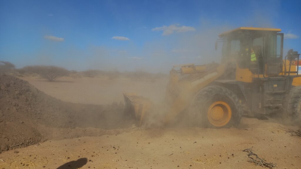
A geotechnical site investigation is not a single activity. It is a staged process in which each step reduces uncertainty and shapes the next one. Done in the right order, it delivers reliable ground data at sensible cost. Done haphazardly, for example by drilling first and thinking later, it produces gaps, wasted money and reports that designers cannot use.
This guide walks through the geotechnical site investigation process from the first desk study to the final report, explaining what happens at each stage, what decisions are made and what a good outcome looks like.
Stage 1: Define the Project and Investigation Objectives
The process starts with understanding what the investigation is for. The geotechnical engineer needs clear information on:
- Type and use of the structure: building, road, bridge, tank, retaining wall, embankment or pipeline
- Size, height and number of storeys, or the length and width for linear works
- Expected loads: column loads, wall loads, floor loads, traffic loads or equipment loads
- Sensitivity to settlement, such as for precision equipment or brittle finishes
- Proposed levels, including cut and fill and basement depths
- Project timeline, budget and constraints
- Applicable codes and client requirements
Poor communication at this stage is a common source of problems. If the geotechnical engineer does not know that the design includes a two-level basement, the boreholes may stop too shallow to be useful.
The outcome of this stage is a clear statement of objectives, such as determining foundation type and bearing capacity, assessing settlement, identifying groundwater conditions or evaluating slope stability.
Stage 2: The Desk Study
The desk study collects and reviews existing information before any equipment arrives on site. It is inexpensive, quick and often the most cost-effective part of the investigation.
Typical sources include:
- Geological maps and memoirs showing rock types, structures and superficial deposits
- Topographic maps and digital elevation models
- Aerial photographs and satellite images, including historical imagery that reveals past land use, quarrying, landfilling or drainage changes
- Previous investigation reports from the site or neighbouring plots
- Hydrological and hydrogeological data, including flood records, borehole logs and groundwater levels
- Soil maps and agricultural surveys
- Records of mining, quarrying or underground works
- Utility records showing buried services
- Seismic hazard information
- Landslide and erosion records
- Local knowledge from neighbours, contractors and municipal engineers
What the desk study achieves:
- Builds a preliminary ground model, an informed guess at likely conditions
- Identifies hazards such as expansive soils, shallow rock, made ground, soft alluvium or unstable slopes
- Highlights data gaps that the fieldwork must fill
- Helps plan borehole locations, depths and test types
- Flags access, safety and environmental constraints
In East Africa, a desk study might quickly show that a site lies on the black cotton soil plains, near a seasonal river, or on a volcanic ash deposit, each of which would change the investigation plan.
Stage 3: Site Reconnaissance
A walkover survey by an engineer or engineering geologist turns the desk study into direct observation.
Observations typically include:
- Topography and drainage: slopes, gullies, ponding, springs, seepage and flow paths
- Vegetation: certain plants indicate wet ground or particular soil types
- Surface soils and rock outcrops
- Evidence of fill, dumping or previous excavation
- Cracks and distress in existing structures, which signal settlement or swelling
- Signs of instability, such as leaning trees, tension cracks, scarps or bulging slopes
- Access for rigs and equipment, including overhead lines, boundary walls and soft ground
- Locations of buried and overhead services
- Neighbouring buildings and sensitive structures
- Health, safety and environmental constraints
Photographs, sketches and notes from this visit become part of the final record. The reconnaissance often leads to adjustments in the planned investigation.
Stage 4: Planning the Ground Investigation
With the preliminary ground model in hand, the engineer designs a tailored investigation programme. This includes:
Exploration points. The number, positions and depths of boreholes, trial pits and probes. Positions are chosen to cover the building footprint, key structural elements, likely variation in ground and areas of concern, such as slopes or former fill.
Methods. The choice between trial pits, auger drilling, cable percussion boring, rotary coring, dynamic probing or cone penetration testing depends on ground type, depth, access and budget.
In-situ tests. Tests such as the standard penetration test, cone penetration test, vane shear or pressuremeter, selected for the soils expected.
Sampling. Disturbed samples for classification, and undisturbed samples for strength and consolidation testing in cohesive soils. Rock cores where rock is encountered.
Groundwater monitoring. Installation of standpipes or piezometers, and a monitoring plan.
Geophysics. Where useful, for example, to map bedrock depth or detect voids.
Laboratory testing schedule. A defined list of tests matched to design needs.
Health, safety and environmental plan. Utility clearance, risk assessments, waste handling, reinstatement and community considerations.
Programme and cost. Time needed, equipment mobilisation and reporting.
The plan should follow recognised standards and guidance, and remain flexible. If early results reveal unexpected conditions, extra exploration points or deeper drilling may be needed. A good specification allows for this.
Stage 5: Fieldwork
Fieldwork is where most of the cost is spent and where data quality is decided. Professional supervision matters.
Setting out. Exploration points are located and marked, and levels recorded. Utilities are scanned and cleared before ground is broken.
Drilling and excavation. Rigs advance boreholes, and excavators dig trial pits. A geotechnical engineer or technician logs the ground as it is exposed, recording soil descriptions, colour, consistency or density, moisture, layer boundaries, groundwater inflows and any unusual features. Logging follows standard systems, such as BS 5930 or equivalent.
In-situ testing. Tests are performed at specified depths or intervals. For SPT, the number of blows needed to drive a sampler is recorded in standard increments. For CPT, continuous electronic data are collected.
Sampling. Samples are collected, labelled, sealed and protected from moisture loss and disturbance. Chain-of-custody records are kept.
Groundwater observations. Water strikes, levels at the end of drilling and levels after stabilisation are recorded. Standpipes or piezometers are installed where long-term monitoring is needed.
Backfilling and reinstatement. Boreholes and pits are backfilled and the site is made safe and tidy.
Quality control. Equipment is calibrated, procedures are followed and field records are checked each day. Inexperienced crews or poor supervision lead to unreliable results, so check credentials.
Seasonal considerations. Groundwater and soil moisture vary with the seasons. If possible, schedule fieldwork to capture critical conditions, and consider follow-up monitoring over the wet season. In expansive soils, moisture condition strongly affects measured properties.
Stage 6: Laboratory Testing
Samples go to a laboratory where tests are carried out according to a defined schedule and recognised standards, such as British, ASTM or national standards.
Common test groups:
- Index and classification tests: natural moisture content, particle size distribution, Atterberg limits (liquid limit, plastic limit, plasticity index), specific gravity and bulk density
- Strength tests: unconfined compressive strength, triaxial tests (undrained and drained) and direct shear tests
- Compressibility tests: one-dimensional consolidation (oedometer) tests to predict settlement
- Swelling and shrinkage tests: free swell, swelling pressure and linear shrinkage for expansive soils
- Compaction and pavement tests: Proctor compaction and California bearing ratio
- Permeability tests
- Rock tests: point load strength, uniaxial compressive strength and slake durability
- Chemical tests: pH, sulphate, chloride and organic content, important for concrete and steel durability
The laboratory should be competent, with calibrated equipment and quality control. Request that results include test conditions and method references.
Stage 7: Data Evaluation and the Ground Model
Once field and laboratory data are in, the engineer interprets them and builds a ground model.
Steps include:
- Compiling borehole and test pit logs into consistent, checked records
- Correlating layers across the site to produce cross-sections and a stratigraphic model
- Interpreting in-situ test results, such as converting SPT N-values to density or strength estimates using established correlations, with appropriate caution
- Selecting design parameters: choosing characteristic values for unit weight, strength, stiffness and compressibility, using statistical and engineering judgement
- Assessing groundwater conditions, including seasonal variation and design water levels
- Identifying hazards: expansive soil, collapsible soil, liquefaction potential, slope instability, corrosive ground, shallow rock or soft layers
- Checking consistency: comparing results with the desk study and geological expectations. Outliers are investigated, not ignored
The ground model is the heart of the investigation. It translates scattered data points into a coherent picture that designers can use.
Stage 8: Geotechnical Analysis and Recommendations
With the model established, the engineer analyses engineering problems relevant to the project:
- Foundation options: shallow footings, raft foundations, piles or ground improvement
- Bearing capacity: ultimate and allowable bearing pressures
- Settlement: immediate, consolidation and differential settlement
- Retaining walls and excavations: earth pressures, support systems and stability
- Slope stability: factors of safety for natural and engineered slopes
- Earthworks: suitability of materials, compaction and embankment design
- Pavement subgrade design: CBR values and layer thicknesses
- Seismic response: site classification and liquefaction assessment
- Groundwater control: dewatering, drainage and waterproofing considerations
- Durability: concrete exposure classes and protection measures
Recommendations should be practical and tied to the proposed development. For example, in black cotton soil, advice might include removing and replacing the swelling layer, founding below the active zone, using piles or designing stiffened rafts with moisture control measures.
Stage 9: The Report
The final geotechnical report brings everything together. A good report is organised, clear and usable.
Typical contents:
- Introduction: project description, objectives and scope
- Desk study findings: geology, history and hazards
- Site description: topography, drainage and observations
- Fieldwork: methods, locations and conditions encountered
- Laboratory testing: summary and results
- Ground model: soil and rock layers, groundwater and cross-sections
- Geotechnical parameters for design
- Foundation recommendations: type, depth, bearing pressures and settlement
- Other recommendations: earthworks, retaining structures, pavements, drainage and slope stability
- Construction considerations: excavation, dewatering, inspection of foundation levels and soil improvement
- Risks and limitations: uncertainties, assumptions and recommendations for further work
- Appendices: borehole logs, test results, location plans, photographs and calculations
Reports often distinguish between factual reports, which present data only, and interpretative reports, which add analysis and recommendations. Clarify which is needed when procuring the work.
The report should be signed by a qualified, responsible engineer, and delivered in time for design to proceed.
Stage 10: Construction Phase Follow-Up
The process does not end when the report is issued.
- Foundation inspections: a geotechnical engineer should verify founding conditions during construction, confirming that actual ground matches the assumptions.
- Monitoring: settlement, groundwater and slope movement may be monitored during and after construction on critical projects.
- Quality control: compaction testing for fills, pile load tests and soil improvement verification.
- Response to surprises: if ground conditions differ from the model, the engineer can adapt the design quickly instead of facing delays and disputes.
Timeline and Planning
Duration depends on scope and access, but a rough sequence for a small to medium project might be:
- Desk study and reconnaissance: a few days
- Mobilisation and fieldwork: days to weeks
- Laboratory testing: one to several weeks, depending on tests such as consolidation or triaxial
- Analysis and reporting: one to two weeks
Build time into the project schedule early. Late geotechnical input is a common cause of design delay.
Common Mistakes in the Process
- Starting fieldwork without a desk study or reconnaissance.
- Failing to share design information with the geotechnical engineer.
- Fixing the borehole plan without flexibility when ground conditions change.
- Poor logging and sampling, which undermines everything that follows.
- Using unaccredited or poorly equipped laboratories.
- Over-reliance on correlations without understanding their limits.
- Producing reports that give data but no usable recommendations.
- Ignoring seasonal effects on groundwater and soil moisture.
- Treating the process as complete at report issue instead of verifying conditions during construction.
Conclusion
A geotechnical site investigation is a structured journey: define the objectives, study what is already known, observe the site, plan the exploration, collect field and laboratory data, build a ground model, analyse engineering problems and document everything in a clear report. Each stage reduces risk and improves the next. Following the sequence, using competent people and keeping communication open between client, designers and geotechnical engineer will give you reliable ground information, economical designs and far fewer surprises on site.
